Cross-sectional analysis
Design · iterative · any section · prestress · P-M diagram
Moment-curvature with limit states, the P-M interaction diagram and load-deflection for any polygon section: standard girders and columns from a preset list or vertices you paste, with any number of rebar layers and bonded prestressing tendons. The section is discretized into layers and solved by iteration, so the section shape is free.
Limit states and design. Patel, D. D., Pleesudjai, C., Neithalath, N., and Mobasher, B. (2026). Limit-state based design of hybrid reinforced UHPC flexural beams using parametric modeling. Engineering Structures, 357, 122353. doi:10.1016/j.engstruct.2026.122353
What you need
- The section: a preset name and its dimensions, or the vertex coordinates of the outline and of a void.
- The concrete laws in tension and compression, imported or typed.
- Rebar layers: depth, area and the bar law. Tendon layers: depth, number of strands, effective prestress and the strand law.
- For load-deflection, the span and loading arrangement of the member.
The module opens with a rectangular default project loaded, so every tab has content from the start.
Step 1 · Section
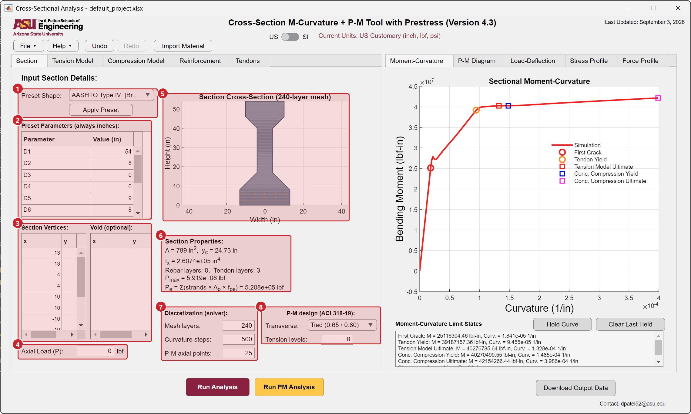
- Preset shape and Apply Preset. Pick a shape from the list (AASHTO Type I to VI, PCI bulb-tees, AASHTO box beams, double tees, the FHWA UHPC pi-girder and multi-stem tee, circular and hollow circular columns, rectangle) and press Apply Preset. The vertices, the standard strand pattern and the section properties are filled in.
- Preset parameters. The dimensions of the chosen shape, always in inches as published by AASHTO and PCI. Edit them and apply again to get a modified shape.
- Section vertices and void. The outline as a list of x, y pairs, counterclockwise, and an optional inner void. Paste your own coordinates here for a custom section and choose Custom as the preset.
- Axial load. The axial force applied with the bending, compression positive, for the moment-curvature analysis.
- The section drawing with the layer mesh, rebar and tendon positions.
- Section properties. Area, centroid, moment of inertia, the number of rebar and tendon layers, the pure compression capacity and the total effective prestress.
- Discretization. The number of layers of the mesh, the number of curvature steps and the number of axial levels of the P-M diagram. The defaults are adequate for design; raise them for a smooth diagram in a publication.
- P-M design. The transverse reinforcement type, tied or spiral, which sets the ACI 318-19 strength reduction factors and the maximum axial load, and the number of tension levels added below zero axial load.
Step 2 · Concrete laws
The Tension Model and Compression Model tabs and the Import Material button are the same as in the Hybrid beam module. The tension law is applied to every layer of the section; a plain concrete section uses a tension law that drops to zero after cracking.
Step 3 · Reinforcement
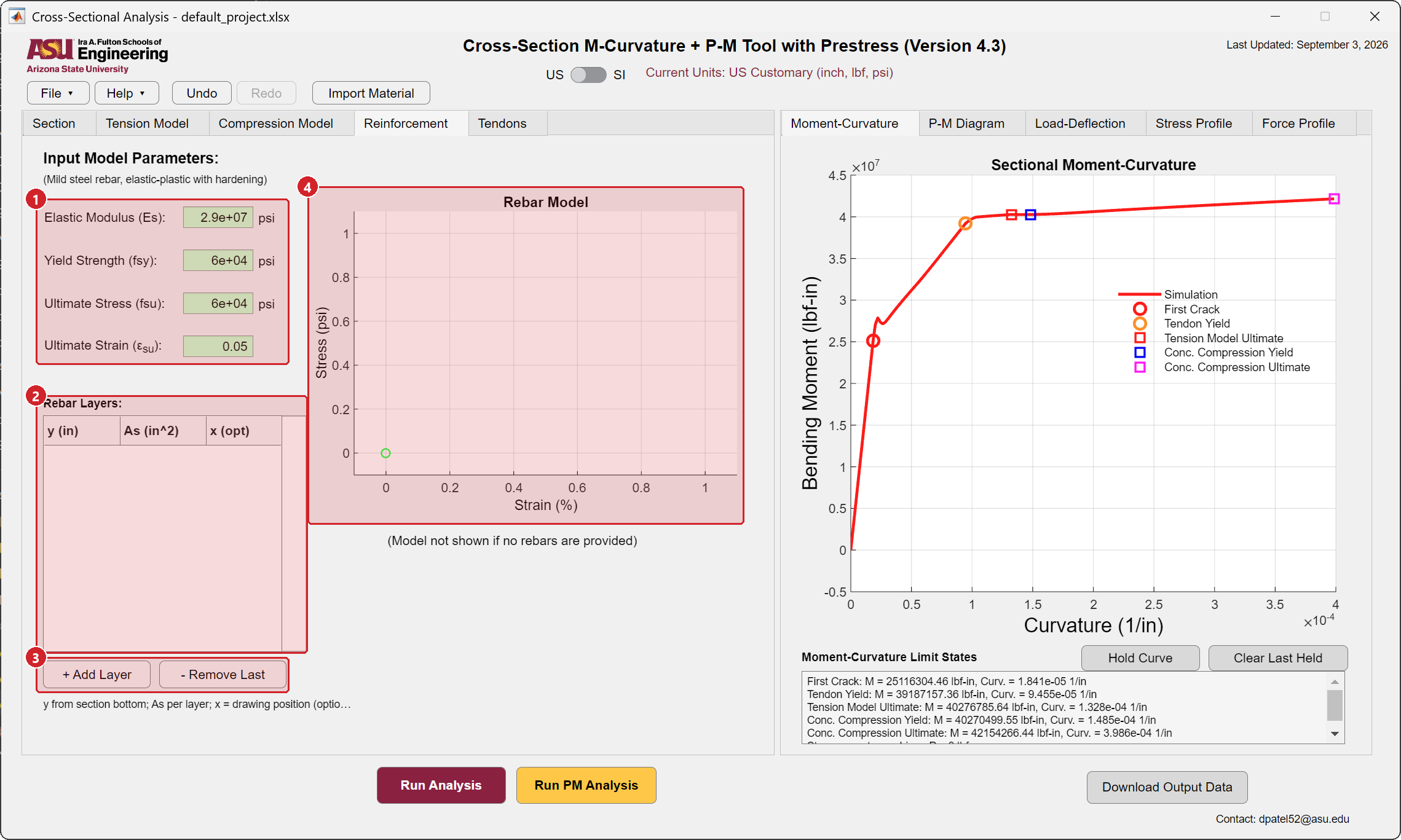
- Rebar law. Modulus, yield strength, ultimate stress and ultimate strain, shared by all layers.
- Rebar layers. One row per layer: height \(y\) from the bottom of the section, total area \(A_s\) of the layer, and an optional x position used only for the drawing.
- Add Layer appends a row, Remove Last deletes the last one.
- The bar law plot, hidden when no layer is defined.
Step 4 · Tendons
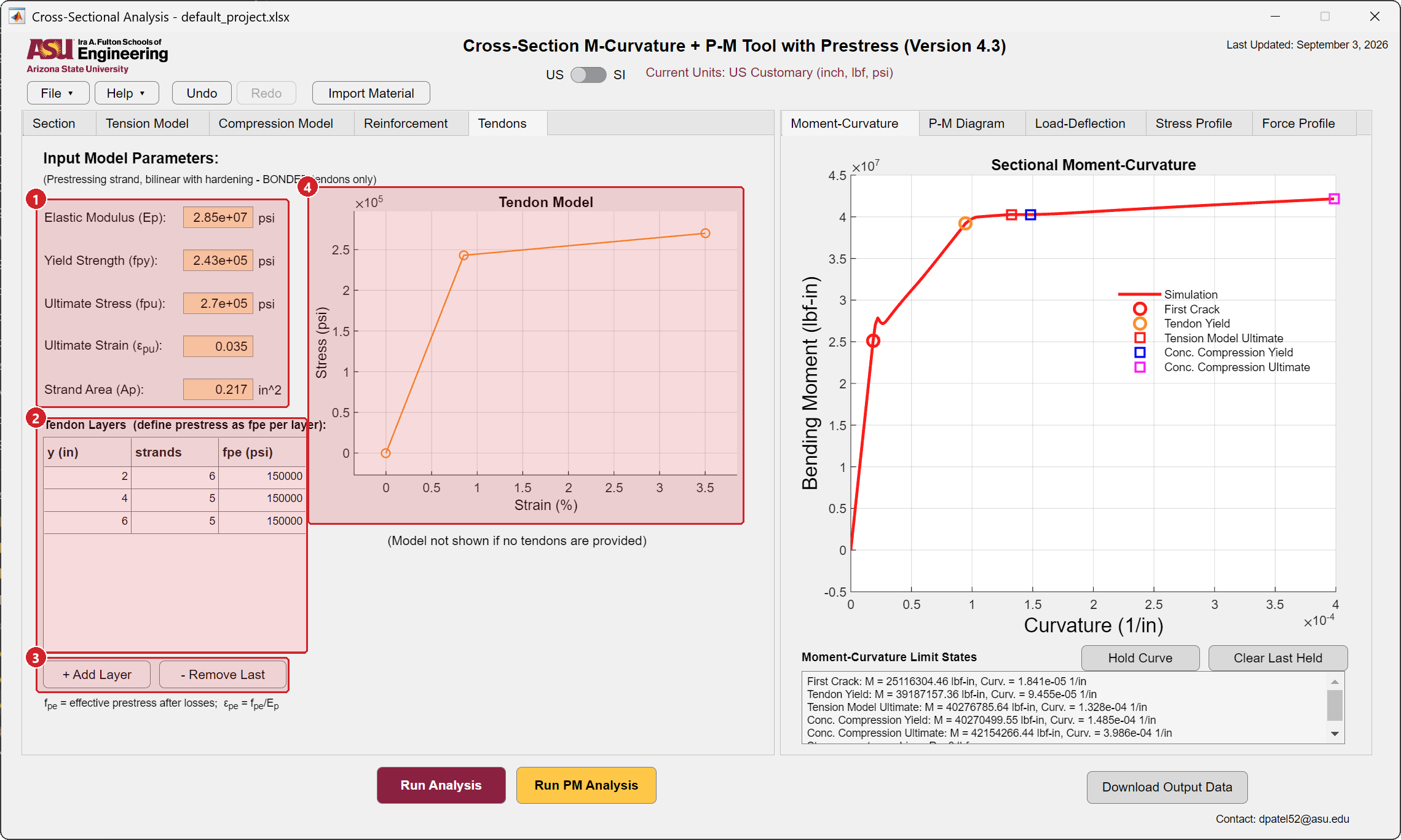
- Strand law. Modulus, yield strength, ultimate stress, ultimate strain and the area of one strand. Bonded tendons only.
- Tendon layers. One row per layer: height from the bottom, number of strands, and the effective prestress \(f_{pe}\) after losses. The prestrain \(\varepsilon_{pe} = f_{pe}/E_p\) is applied to each layer before bending. Losses are entered by you through \(f_{pe}\); the module does not compute them.
- Add Layer and Remove Last.
- The strand law plot.
Step 5 · Run Analysis, moment-curvature and limit states
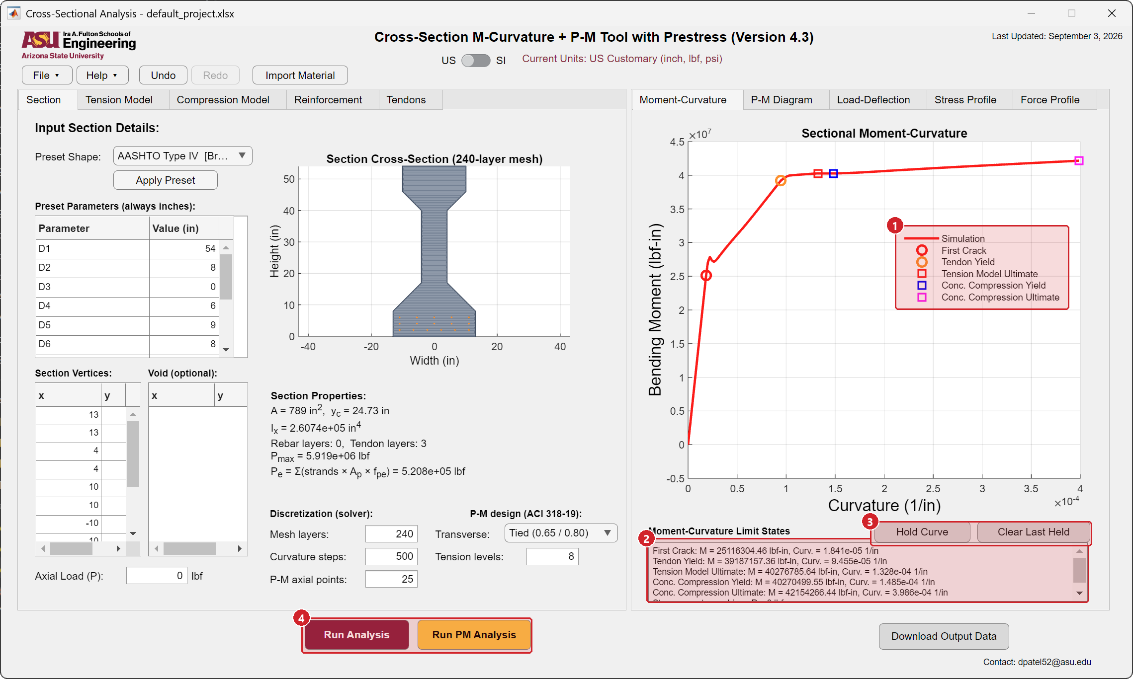
- Limit states. Decompression, first crack, service stress, rebar yield, tendon yield, tension model ultimate, compression yield, compression ultimate, and rebar or tendon rupture, each marked when it is reached.
- Their values, and the reason the curve stops: crushing, rupture, or loss of equilibrium.
- Hold Curve and Clear Last Held. Hold keeps the current curve on the plot while you change inputs and run again, up to ten curves, for a parametric study. Clear Last Held removes the most recent one.
- Run Analysis (F5) recomputes after any change. A label above the buttons reminds you when inputs changed since the last run.
Step 6 · Run PM Analysis, the interaction diagram
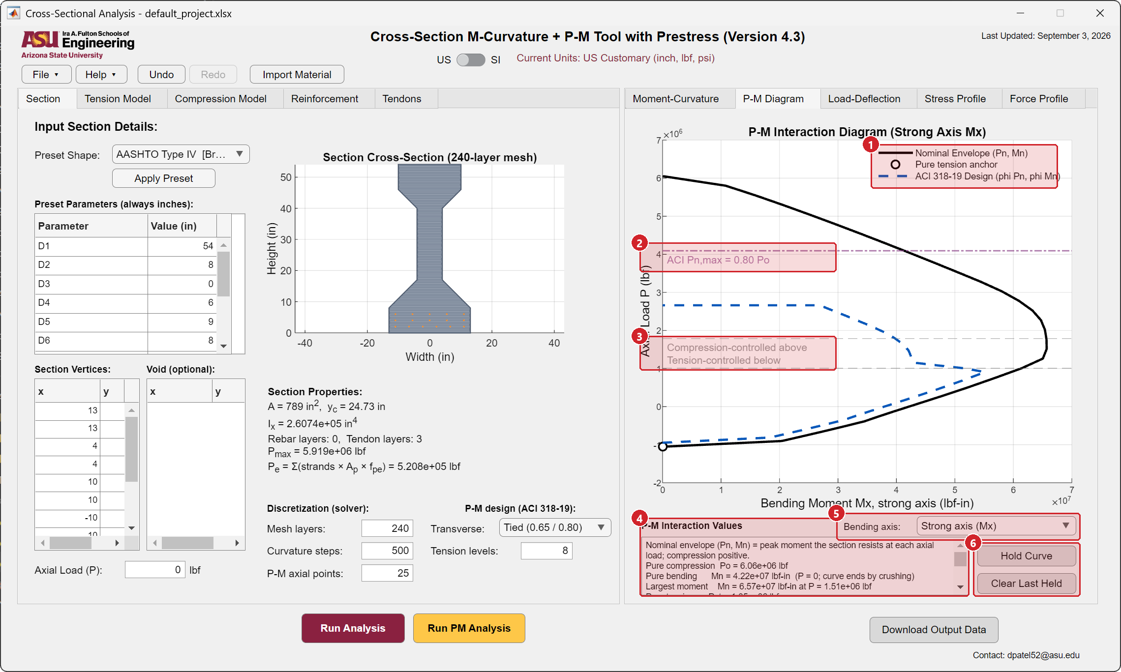
- Legend. The nominal envelope \((P_n, M_n)\), the pure-tension anchor, and the ACI 318-19 design curve \((\phi P_n, \phi M_n)\).
- Maximum axial load. The ACI cap at 80 percent (tied) or 85 percent (spiral) of the pure compression capacity.
- Compression- and tension-controlled regions, separated at the balanced condition of ACI 318-19.
- Values. Pure compression, pure bending, the largest moment and the axial load at which it occurs, and pure tension. Axial levels at which equilibrium could not be reached are listed here instead of being drawn.
- Bending axis. Strong axis \(M_x\) or weak axis \(M_y\); the analysis is rerun about the chosen axis.
- Hold Curve and Clear Last Held for comparing diagrams.
Each point of the envelope is the peak moment along the moment-curvature path at that axial load. The diagram takes from a few seconds to a minute depending on the mesh, the curvature steps and the number of axial points.
Step 7 · Load-deflection
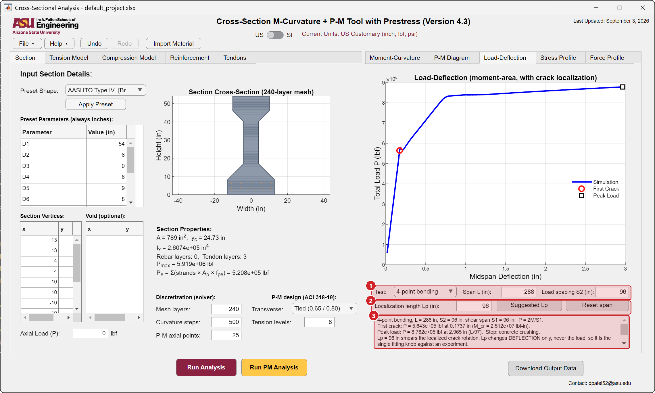
- Test arrangement. Four-point or three-point bending, the span and the load spacing. Reset span restores the default proportions.
- Localization length. The plastic length of the member. Suggested Lp writes the constant-moment zone for four-point bending or the section depth for three-point bending. It changes the deflection after the peak only, never the load.
- Summary. Shear span, first-crack and peak loads with their deflections, and the reason the curve stops.
The Stress Profile and Force Profile tabs draw the strain, stress and force distributions through the depth at any curvature step, with the rebar and tendon forces.
Step 8 · Export
Download Output Data writes the workbook with the section vertices, the rebar layers, the moment-curvature curve and the limit states. File → Save keeps the project.
Worked example
Apply the AASHTO Type IV preset. The preset carries three strand layers with an effective prestress of 150 ksi. Press Run Analysis: the curve starts at the decompression state, shows first crack, tendon yield, tension model ultimate, compression yield and compression ultimate, and stops at crushing. Press Run PM Analysis to draw the envelope and the ACI design curve. Then set the axial load on the Section tab to a compressive value, run again, and hold the curve to compare the two responses.