Run your first example
Getting started · 2 of 6
Open the supplied ASTM C1609 project, inspect its fitted load–deflection curve, and export the results. The file includes the beam, test data and fitted material law; you do not need to prepare data or run Auto-Fit first.
What you need
- HRC Designer installed and starting. See Install and first launch.
- The project file for this walkthrough: ASTM_C1609_first_example_SI.mat. Download it before you start and remember where you put it.
Use the project linked above
The supplied file uses the version 4.3 project format and matches the inputs and result screenshots below. Open it with File → Open. Open Example Project may load a different reference specimen.
Step 1 · Open the ASTM C1609 module
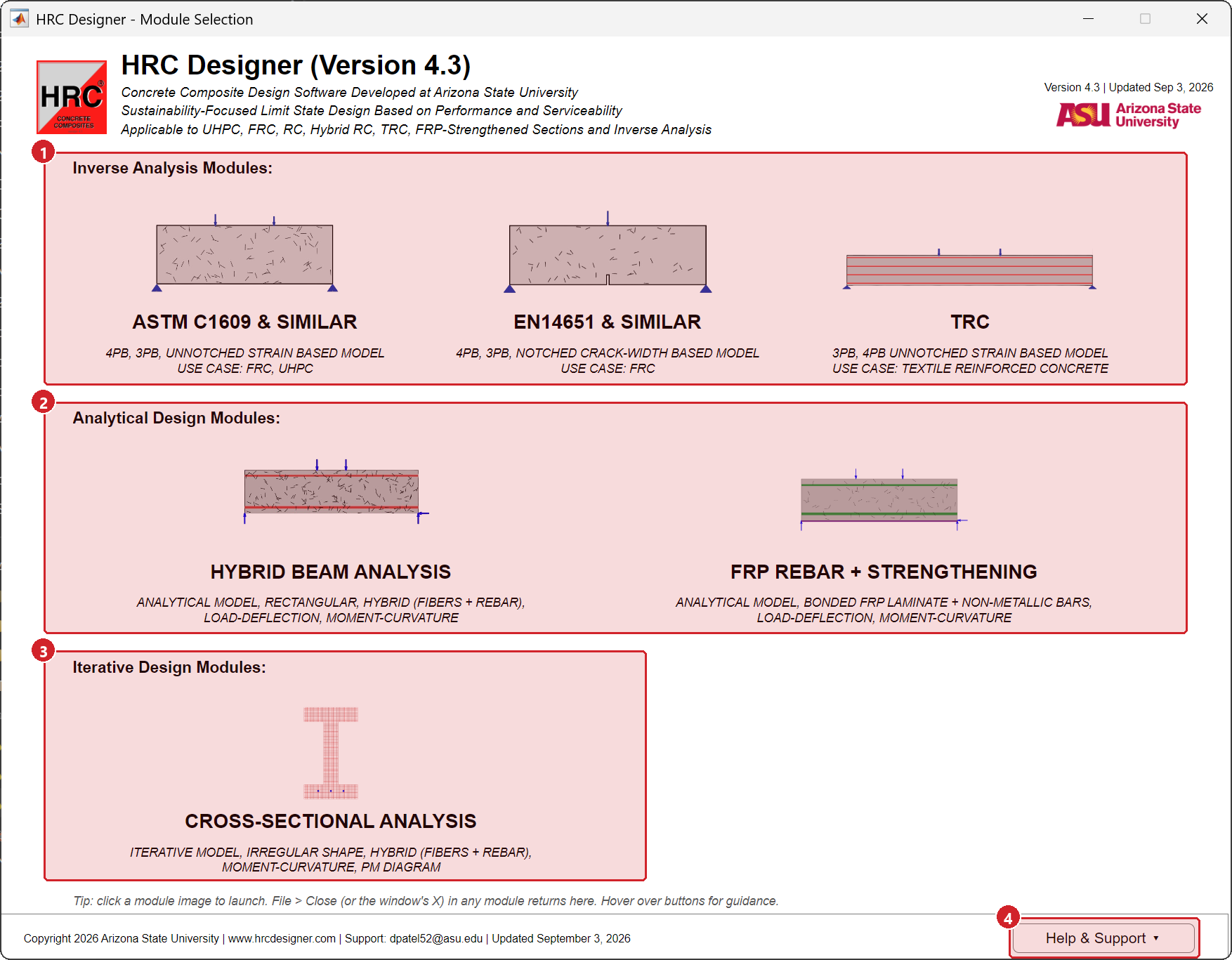
Start HRC Designer from the Start menu. The module selector opens. Click ASTM C1609 & similar in the Inverse analysis group.
Step 2 · Open the project file
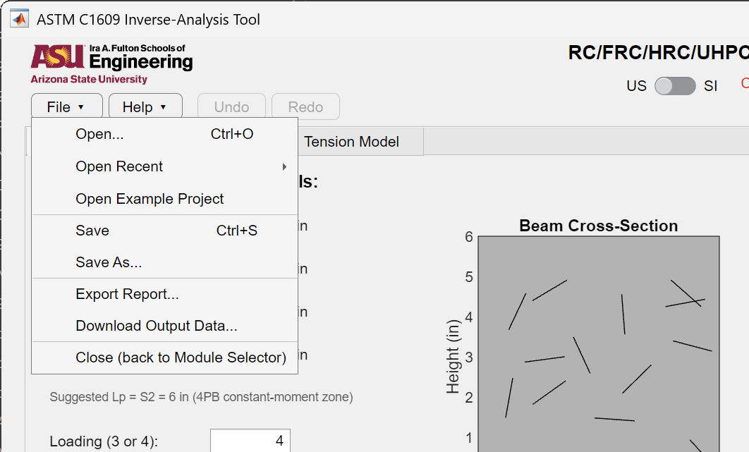
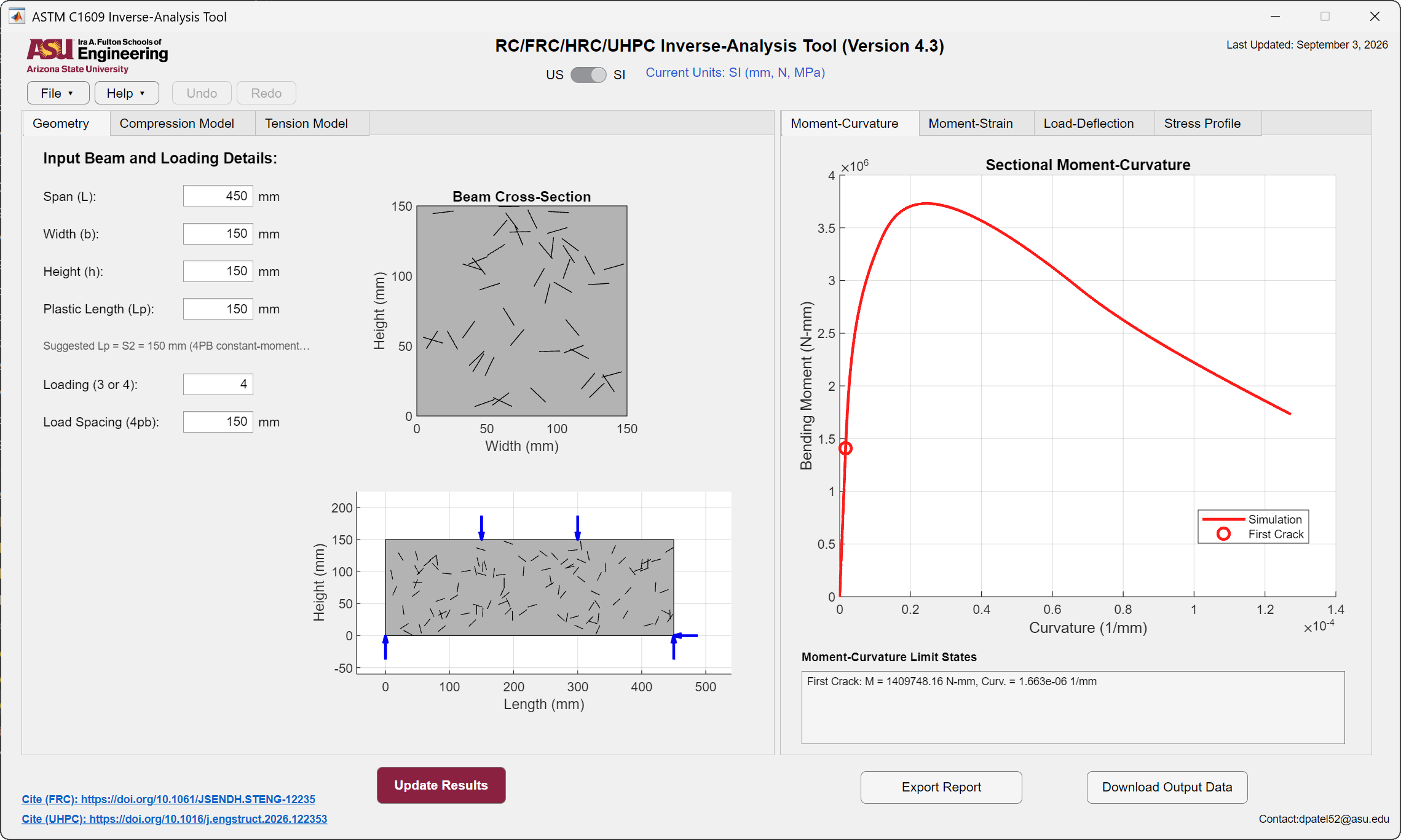
Choose File → Open and select ASTM_C1609_first_example_SI.mat. The module fills in with:
- a beam 150 × 150 mm in section on a 450 mm span, four-point bending with a load spacing of 150 mm and a plastic length of 150 mm, in SI units;
- a tension law, \(E\) = 20 000 MPa, \(\varepsilon_{cr}\) = 0.0125 percent, stresses 2.88, 1.25 and 0.375 MPa at strains 0.125, 0.875 and 1.75 percent, together with the compression law it was fitted with;
- the measured load-deflection record of that beam, 92 points with a peak load of 51.3 kN, already loaded as the active experimental curve.
The unit switch in the header follows the file and moves to SI. Check it against the Geometry and Tension Model tabs: every input above is visible on screen, so a mismatch shows up immediately.
Step 3 · Compute
Press Update Results, or F5. Every result tab is recomputed from the inputs now on screen. This takes a moment on the first run of a session.
Step 4 · Read the Load-Deflection tab
Open the Load-Deflection result tab. This is the comparison that matters in an inverse analysis: the measurement and the model on the same axes.
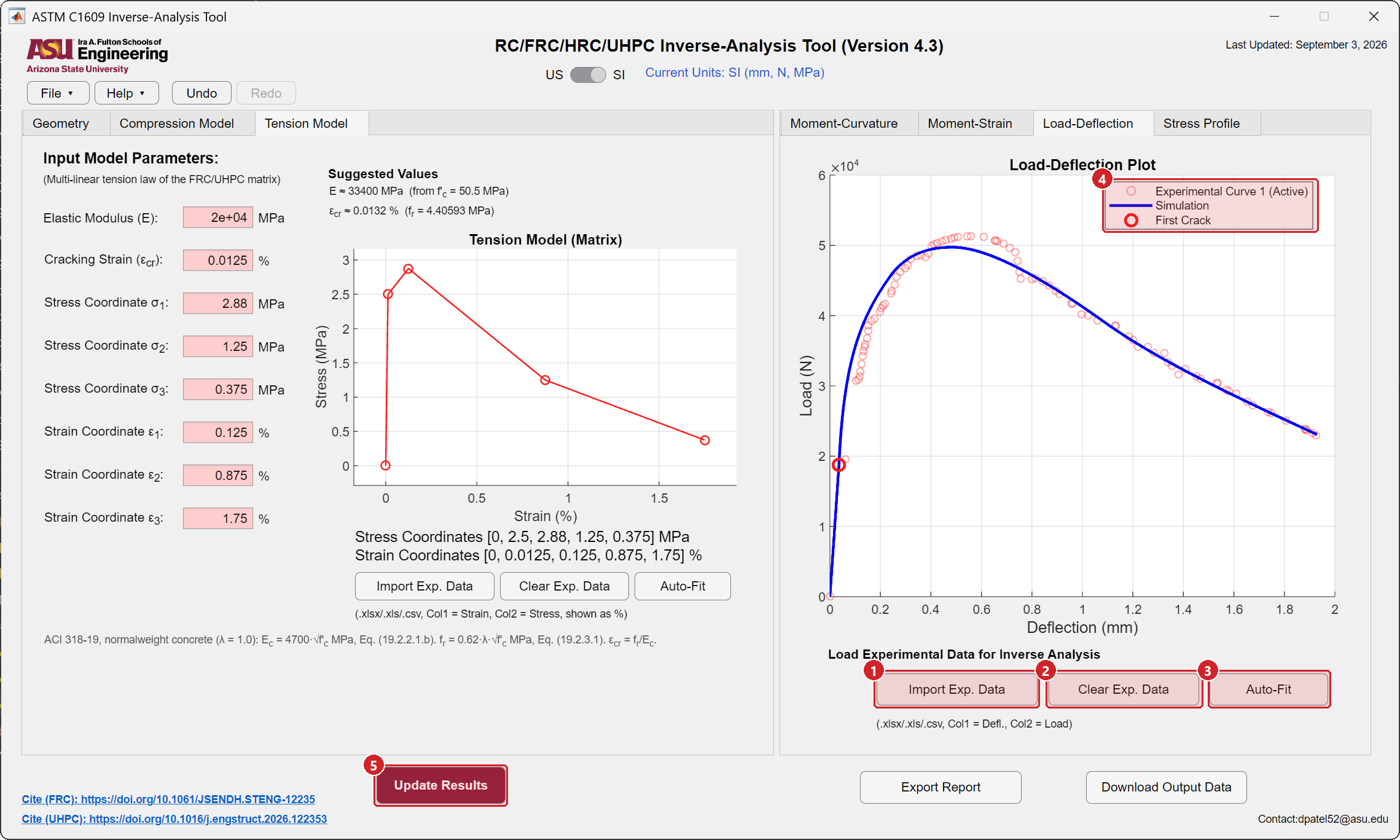
What you should see: the simulated curve rising with the measured points through the first-crack region to a peak near the measured 51.3 kN, then following the measured softening branch to the end of the record. The two curves should stay close over the whole range rather than crossing once and diverging.
If they are far apart, something in the inputs differs from the file. Check the span, the width, the height and the load spacing on the Geometry tab, the position of the US / SI switch, and the tension law on the Tension Model tab, in that order. Reopening the downloaded file restores all three at once.
The other result tabs are computed from the same law. Moment-Curvature shows the section response with its limit states, Moment-Strain colors each part of the curve by the branch of the tension law that controls it, and Stress Profile draws the strain and stress distributions through the depth at a strain you choose. They are described step by step on the ASTM C1609 page.
Step 5 · Save the session and export the results
- File → Save writes the whole session, inputs, material laws, imported curve and unit system, into one project file. File → Open brings it back.
- Export Report writes a single HTML file with the material laws, the limit states and every figure. Open it in a browser and print to PDF from there.
- Download Output Data writes an Excel workbook with one sheet per curve and an
Input_Parameterssheet holding every input.
Details of all three files are on Projects, reports and output data.
Where to go next
- Carry the material into a design module. The
Input_Parameterssheet of the workbook you just wrote is the material exchange format. Open the Hybrid beam, FRP or Cross-sectional module and choose File → Import Material to take the tension and compression laws across. A matching material workbook for this beam, holding theTension_Data,Compression_DataandInput_Parameterssheets only, is available as material_ASTM_C1609_example.xlsx. - Use your own test. Prepare a two-column file, deflection then load, as described under Test data files, then follow the full ASTM C1609 instructions from Step 1.
- Fit a law yourself. This project is supplied already fitted so that the first run succeeds without an inverse analysis, but the inverse analysis is the point of the module. Type any rough tension law over the one in the boxes, press Auto-Fit on the Load-Deflection tab and compare the result with the values listed in Step 2. See Step 5 · Auto-Fit and Auto-Fit, the inverse analysis.
- Notched prisms instead. A notched specimen tested to a load-CMOD record goes to the EN 14651 module. Read the version note at the top of that page first.