Material models and notation
Background · 1 of 5
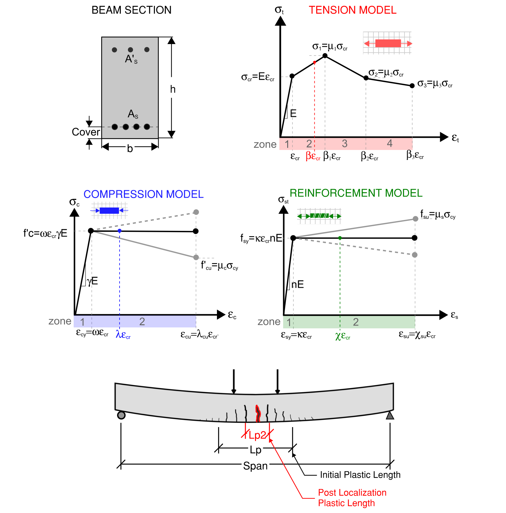
The input boxes of every module are the coordinates of piecewise-linear stress-strain laws. Internally the software scales all of them by the cracking stress and the cracking strain of the matrix, which is what makes one closed-form solution serve concrete, UHPC, fibers, rebar and textiles alike.
Tension law of the matrix
A quadrilinear curve through the origin. The elastic branch ends at the cracking strain. Three post-cracking coordinates follow. Their stresses are entered directly in the software and are multiples of the cracking stress inside the model:
A strain-hardening material such as UHPC has \(\mu_1 > 1\). A strain-softening FRC has \(\mu_1 < 1\). The last coordinate \(\varepsilon_3\) is the strain at which the tensile stress is taken as exhausted.
In the notched-beam module the same three post-cracking coordinates are defined against crack width instead of strain, \((w_1, \sigma_1), (w_2, \sigma_2), (w_3, \sigma_3)\), and the elastic branch keeps \(E\) and \(\varepsilon_{cr}\). The stress-crack width law is a property of the single crack that forms at the notch. That \(w\) is the crack opening inside the ligament, measured from first cracking; it is smaller than the CMOD recorded at the notch mouth by the notch amplification, so a \(w_3\) of 2.5 mm can carry a test that reached a measured CMOD of 3 mm.
Compression law
Elastic up to the compressive strength, then linear to a residual stress at the maximum strain:
The four inputs are \(E_c\), \(f'_c\), \(f'_{cu}\) and \(\varepsilon_{cu}\). Set \(f'_{cu} = f'_c\) for an elastic-perfectly plastic law. The normalized form uses \(\gamma = E_c/E\), \(\omega = \varepsilon_{cy}/\varepsilon_{cr}\), \(\mu_c = f'_{cu}/f'_c\) and \(\lambda_{cu} = \varepsilon_{cu}/\varepsilon_{cr}\).
Reinforcement law
Rebar is bilinear: elastic with modulus \(E_s\) up to the yield strain, then a hardening or softening branch to the ultimate strain. Normalized: \(n = E_s/E\), \(\kappa = \varepsilon_{sy}/\varepsilon_{cr}\), \(\mu_s = f_{su}/f_{sy}\) and \(\chi_{su} = \varepsilon_{su}/\varepsilon_{cr}\). FRP bars and laminates are linear-elastic to rupture. Textile layers in the TRC module are treated as tension-only layers with their own bilinear law.
Notation used in the manual
| Symbol | Meaning | Software input |
|---|---|---|
| \(b, h\) | Section width and depth | Geometry tab |
| \(L\) | Span between supports | Span (L) |
| \(S_2\) | Distance between the two loads in 4-point bending | Load Spacing (4pb) |
| \(L_p\) | Plastic length, the zone over which post-peak curvature localizes | Plastic Length (Lp) |
| \(d_n\) | Notch depth, notch tip down to the CMOD gauge line, notched beam only | Notch Depth |
| \(E, \varepsilon_{cr}\) | Tensile modulus and cracking strain of the matrix | Elastic Modulus (E), Cracking Strain |
| \(\sigma_i, \varepsilon_i\) | Post-cracking tension coordinates | Stress Coordinate, Strain Coordinate |
| \(\sigma_i, w_i\) | Post-cracking crack-width coordinates, on the internal crack opening | Stress Coordinate, Crack Width |
| \(E_c, f'_c, f'_{cu}, \varepsilon_{cu}\) | Compression law | Compression Model tab |
| \(\beta\) | Normalized tensile strain at the bottom fiber, \(\varepsilon_{t}/\varepsilon_{cr}\) | Bottom tensile strain |
| \(k\) | Neutral axis depth ratio, depth of the neutral axis divided by \(h\) | Reported on the Stress Profile tab |
| \(M, \phi\) | Bending moment and curvature | Moment-Curvature tab |
| \(f_{LOP}, f_{R1} \ldots f_{R4}\) | EN 14651 limit of proportionality and residual flexural strengths | Flexural Stress-Crack Width tab |
Suggested values
When no direct tensile test is available, the Tension Model tab prints starting values from the compressive strength entered on the Compression Model tab, following ACI 318-19 for normalweight concrete:
They are printed beside the inputs and are never applied automatically. The plastic length is suggested as the constant-moment zone \(S_2\) in 4-point bending, the section depth \(h\) in 3-point bending, and 25 mm for the EN 14651 notched prism.